What is shadowless and shadow-casting or directional illumination in Machine Vision
Published on: Mar 24, 2025

Written by: Soumen das
Introduction
Machine vision systems critically depend on lighting to capture high-quality images for inspection. The way a target is illuminated determines whether features of interest appear with sufficient contrast and clarity. In automated optical inspection (AOI), two broad lighting approaches are shadowless illumination and shadow-casting (directional) illumination. Shadowless lighting refers to diffuse, uniform light that produces virtually no shadows on the object, whereas directional or “shadow” lighting uses one or few light angles and often casts visible shadows on uneven surfaces.
Lighting Principles in Machine Vision
Effective illumination is a prerequisite for obtaining high-quality images in visual inspection. Different inspection tasks demand different lighting geometries. Broadly, lighting setups can be categorized as shadowless (diffuse) or shadow-forming (directional). Below we explain each principle and illustrate how light arrangement influences imaging outcomes.
What is Shadowless Illumination (Diffuse Lighting)
Shadowless illumination involves flooding the scene with light from many directions such that no distinct shadows are formed. In machine vision LED lighting, common shadowless designs include dome lights (hemispherical “cloudy day” illuminators), flat diffuse panels, multi-directional ring lights, and other diffuse enclosures. The key characteristic is highly diffuse, omnidirectional light that uniformly bathes the target. This eliminates harsh highlights and shadows, making the lighting extremely even across the field of view. Shadowless lighting is widely used for inspections that require uniform brightness and minimal glare, such as reflective surfaces, transparent materials, finish checks, optical character recognition (OCR) on, inspecting for presence/absence of components, and any task needing high image uniformity.
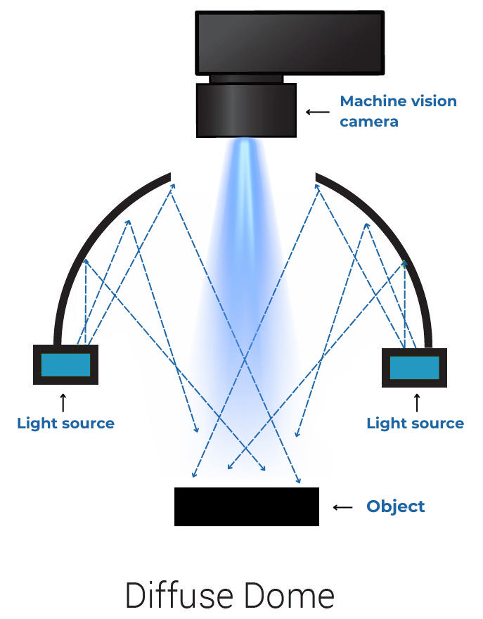
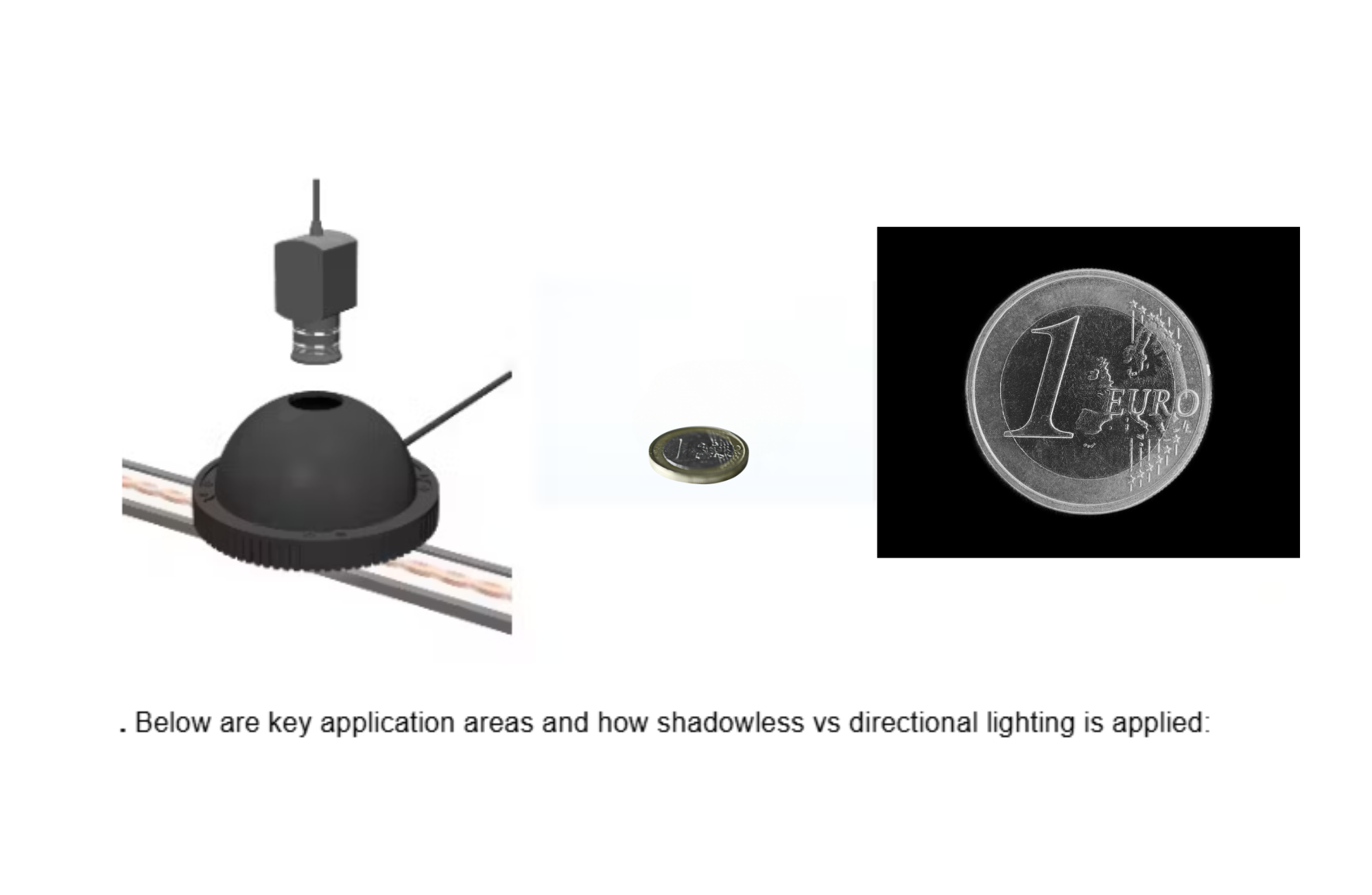
Figure 1: A diffuse dome light provides shadowless illumination by reflecting and scattering LEDs’ output over a hemispherical cavity. Light (blue rays) reaches the object from all angles, eliminating directional shadows. Dome lights are a classic design for uniform, “cloudy sky” illumination.
Because shadowless sources subtend a large solid angle over the object, they are most effective when placed close to the target. A dome or diffuse panel very near the part produces a broad range of incident angles, “wrapping” the light around features. This tends to flatten the appearance of textured or uneven surfaces – effectively minimizing surface relief in the image. For example, uniform diffuse lighting can make an uneven or bumpy surface appear flat, which is useful for reliably imaging printed codes or text without interference from shadows or glare. Highly specular (shiny) objects also benefit: a diffuse light mitigates point-source reflections that would otherwise obscure details.
In summary, shadowless illumination excels at providing even lighting and reducing glare, at the cost of washing out depth cues like shadows.
Directional (Shadow-Casting) Illumination
Shadow-casting illumination uses one or more light sources at specific angles, rather than from all around. Here the light has strong directivity, so raised features will cast shadows onto lower surfaces. Nearly all traditional machine vision lights – ring lights, bar lights, spot/projector lights, low-angle “dark field” lights, coaxial lights, etc. – fall into this directional lighting category. The defining trait is that the illumination comes primarily from one direction or a limited set of directions, rather than being diffusely scattered from everywhere. As a result, any height variations on the target produce shade or highlight patterns (shadows or bright glints) that reveal the object’s 3D structure.
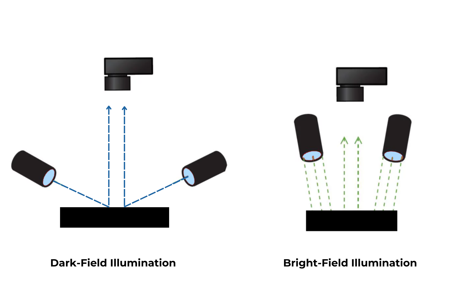
Figure 2: Directional lighting (partial bright-field). Two light sources at high angles illuminate a surface. Because light arrives from limited directions, protrusions or dents can cast shadows (dashed green rays indicate light paths). Such shadow lighting enhances topographical contrast.
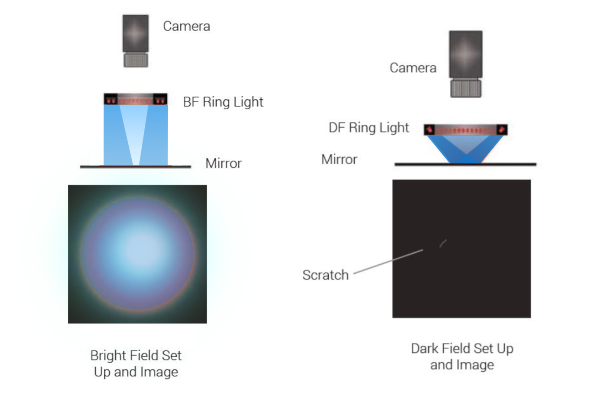
Unlike a dome that lights the object from all sides, a directional setup might illuminate only one side. This can create regions of shadow opposite the light source and bright reflections on the facing side. While this non-uniformity may seem like a drawback, it is extremely useful for highlighting surface irregularities. Tiny scratches, bumps, or edges that would be invisible under flat lighting often become conspicuous under angled light due to the shadow or glare they produce. For example, in dark-field illumination (a subset of directional lighting), lights at a very low angle cause a smooth surface to appear dark, but any scratch or particle catches light and glows bright against the dark background.
Thus, directional lighting is often chosen to detect micro-defects such as scratches, cracks, or solder fillet shapes – features where contrast arises from the presence of shadows or specular highlights. The trade-off is that areas not directly lit may be under-illuminated or hidden behind other features (occluded by shadows), so multiple lights or camera views might be needed to inspect all sides of a complex part.
 Illumination (1).png)
Bright-Field vs. Dark-Field Illumination
In machine vision practice, directional lighting can be further classified by lighting geometry- how we install lights.
What is Bright-field illumination?
Bright-field illumination is a lighting geometry in machine vision where the light source is directed onto the object from angles typically between 90° and 45° relative to the imaging object. This setup produces strong, uniform reflection from flat surfaces, making it ideal for highlighting surface features such as printed text, color variations, or overall shape and contrast.
What is Dark-field illumination?
Dark-field illumination is a technique where light is projected onto the object from low, shallow angles, close to the imaging object—typically between 0° and 45° off the imaging surface. This method minimizes direct reflections and enhances edges, scratches, or surface defects, especially on highly reflective or textured surfaces. It is often used to detect subtle flaws that are not visible under bright-field lighting.
In summary, Bright-field typically means lighting from near the camera axis (on-axis or high-angle lighting) resulting in a brightly lit field of view. Whereas the Dark-field illuminates the object from the side of the object, lower lighting angle and away from the camera.
In practice, engineers often try both to see which gives the best contrast for the defect or feature of interest
Design and Integration in AOI Systems
The design of illumination hardware and its integration into automated optical inspection systems are driven by the need to achieve the right lighting geometry for the given inspection – often within tight space and speed constraints. Modern AOI machines for electronics typically combine multiple light sources of different types and angles to maximize defect visibility.
For instance, a single AOI station may have an axial (coaxial) light for shadowless top-down illumination and several angled ring lights for directional illumination from the sides. Many advanced PCB inspectors use a dome or diffused on-axis light plus low-angle lights in various colors. This allows the system to capture multiple images under different lighting – essentially leveraging both shadowless and shadow-casting illumination in one system. A classic example is solder joint inspection: the machine might sequentially flash red, green, and blue LED rings at 45° and 30° angles and also use a diffuse overhead light. Each lighting reveals different aspects of the solder’s shape and fillet quality, and the combined information leads to a more reliable inspection. In other words, hybrid lighting designs are common, marrying the uniformity of diffuse lights with the contrast-enhancing effects of directional lights.
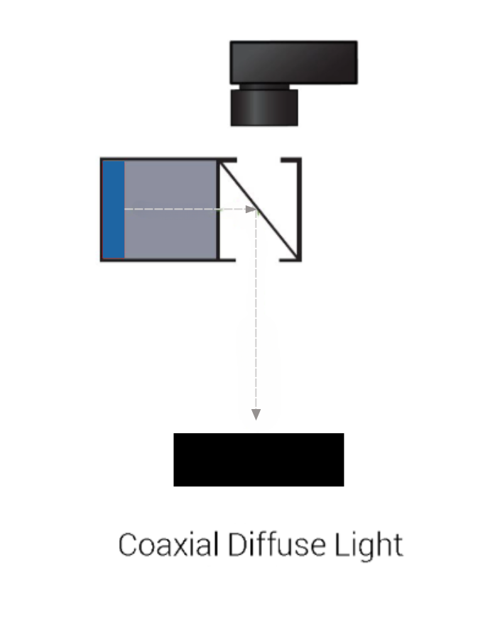
From a hardware perspective, shadowless lights like domes traditionally posed mechanical integration challenges. A standard dome is a bulky half-sphere that sits close to the object, often with a hole in the top for the camera lens. This can constrain camera positioning and leave a dead spot (shadow) directly under the lens opening. Newer innovations such as flat dome lights address this by using a thin, clear diffuser plate with micro-structured reflectors to create the dome effect without a physical dome. These flat diffuse lights provide high uniformity and shadow-free illumination in a compact form factor, eliminating the central dark spot caused by a traditional dome’s camera hole. This is especially advantageous in compact vision systems or when the camera needs more working distance and flexibility. For example, raising a flat dome light further from the object increases collimation (making it act a bit more like a directional source) to emphasize certain features, without the light loss that a beam-splitter in coaxial lights would introduce. On the directional lighting side, design considerations include the angle, number, and placement of sources. Low-angle ring lights (sometimes called “quadrant” or “multi-sided” lights) are designed to graze light across surfaces from the side, which is excellent for catching height deviations like scratches or embossed markings. Coaxial lights use a beam-splitter to shine light directly along the camera’s optical axis for very flat illumination of planar surfaces – useful for detecting print on mirror-like surfaces or looking for subtle contrast differences on a flat background. The wavelength of lighting is another design factor: selecting color or even infrared/UV can enhance certain contrasts (for instance, using red light to make a copper solder fillet stand out on a green PCB).
In summary, AOI lighting subsystems are often carefully engineered combinations of diffused and directional lights, sometimes in multi-ring assemblies, to ensure that all necessary features – from printed text to microscopic scratches – can be detected in one automated sequence.
Integration must also consider the production environment. In electronics and medical device manufacturing, inspection often happens in high-speed, high-volume settings, so lights may need to be strobed at high intensity to “freeze” moving parts on fast conveyors.
Medical and pharmaceutical inspections may impose additional requirements like minimal heat generation (to maintain sterile or safe conditions) and compatibility with cleanrooms.
Lighting units for these industries are typically LED-based for low heat and long life, and may be enclosed to avoid particulate generation. All these design principles – geometry, angle, diffusion, wavelength, timing, and packaging – are balanced to deliver consistent, high-contrast images suitable for automated analysis.
Application in Electronics Inspection
Electronics manufacturing relies heavily on machine vision for quality control, and lighting techniques are tailored to the features being inspected. Two major use cases in this domain are printed circuit board (PCB) assembly inspection (solder joints, component placement, etc.) and semiconductor or component surface inspection. We compare how shadowless and directional lights are applied:
- Uniform PCB Illumination for Presence/Absence and OCR: When the goal is to verify that all components are present and correctly placed on a PCB, or to read identification markings (labels, barcodes, chip text), shadowless lighting is often preferred. A diffuse dome light or coaxial illuminator can evenly light a populated board without glare from shiny solder or metal, and without shadows from tall components falling onto neighboring parts.
For example, in a PCB assembly, tall connectors or capacitors could cast shadows on nearby small chips if lit from one side. A dome light solves this by illuminating from all around, eliminating occlusion shadows. This high uniformity is also crucial for machine reading of printed text or codes on components. Any specular highlights or shadows could confuse an OCR algorithm, so using a full bright-field diffuse source makes the markings uniformly visible.
Coaxial lights are also used for inspecting solder paste prints or semiconductor wafer surfaces – essentially shadowless from the camera’s perspective – to detect printing defects or scratches on a flat surface with minimal interference from texture.
- Angled Lighting for Solder Joints and Surface Defects: Many PCB inspections target solder joint quality (e.g. detecting unsoldered leads, shorts, or poor fillets) and small part defects. Here, shadow-casting illumination is essential because the shape and height of solder fillets need to be inferred from how they reflect light. A common approach in solder joint inspection is to use multi-angle ring lights – for instance, a system may use three tiers of LEDs at different angles (low, medium, high) and capture multiple images.
The lowest-angle lighting will highlight solder fillet edges (showing lifts or tombstoning parts as distinct shadows), while a higher-angle light might better illuminate the pad underneath and solder meniscus. By analyzing the composite, the system can classify the joint. In one documented technique, three ring-shaped LED arrays at different angles were used to acquire three images of each solder, enabling detection of solder shape anomalies with high accuracy.
Directional lighting also helps to inspect for micro-defects on PCB surfaces, like hairline scratches on a connector or cracks in a resistor, which appear as bright or dark lines under the right low-angle illumination.
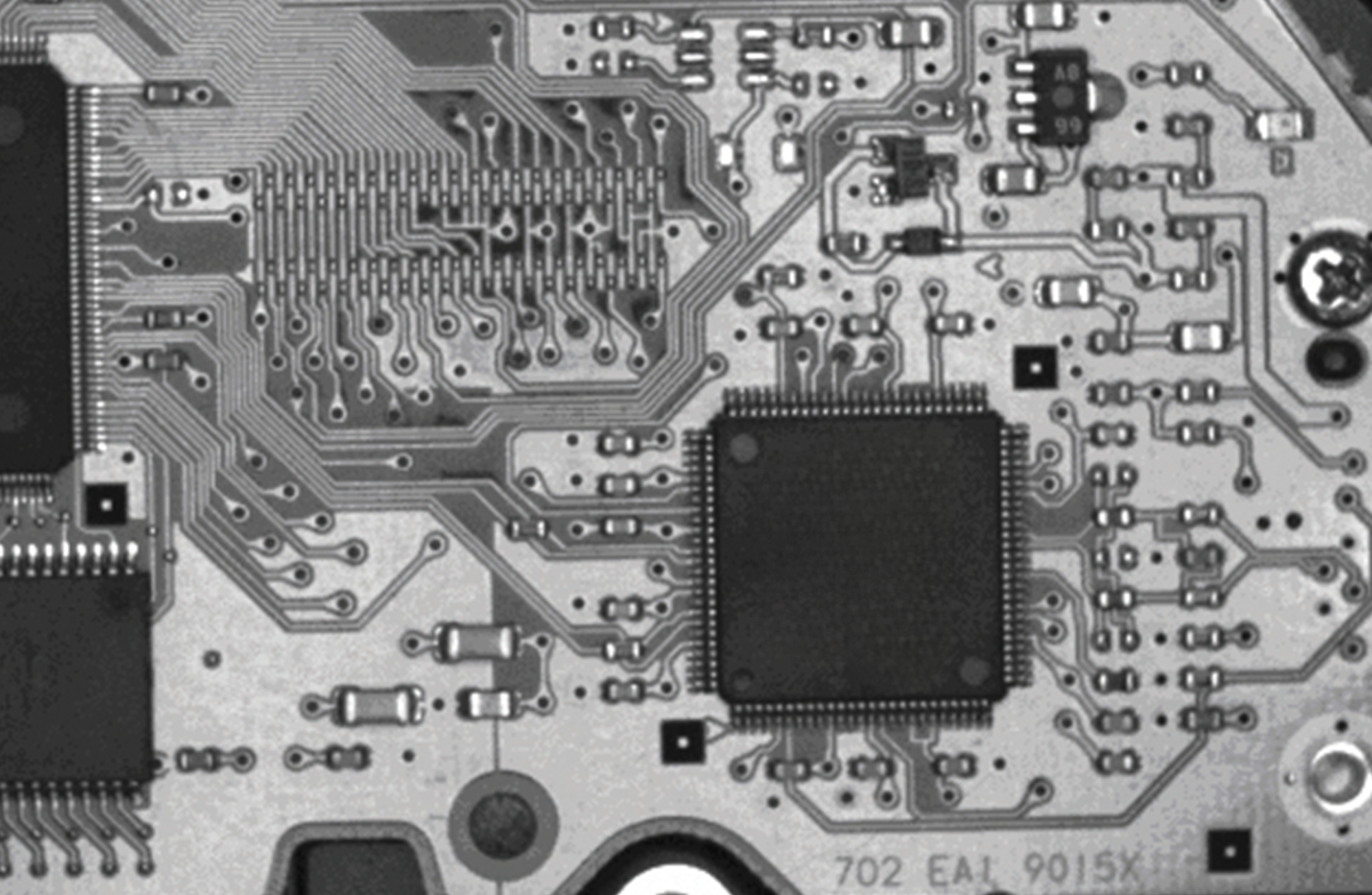
A concrete example of combining lighting methods is inspecting a PCB with reflective surfaces (like a disk drive controller board with a metallic screw or solder pads). Using only a high-angle ring light in bright-field caused glare that obscured detail on the shiny board coating. The solution was to employ full diffuse illumination – either a dome or coaxial light – to eliminate those specular reflections. In a demonstration, a white dome light produced a very uniform image of the PCB, clearly showing all components with no glare. However, the diffuse light by itself made it harder to see the missing screw in one corner, because the contrast between the screw’s presence/absence was subtle. When a coaxial (on-axis) light or a more directional red light was used, the missing brass screw stood out with higher contrast (the screw’s pad reflected red light differently than the green PCB background).
This underscores a general point: shadowless lighting excels at uniformly revealing all features, while directional lighting can amplify specific feature contrasts. In practice, combining them – e.g. using a diffuse dome to ensure nothing is hidden, plus an angled light to enhance critical defect contrast – yields the best results.
Another scenario is inspection of electronic connectors or pins for bend or coplanarity defects. If you illuminate a row of pins straight-on (shadowless), it may be hard to tell if one pin is slightly bent upward. But an angled light from the side will cast a longer shadow for a taller (lifted) pin compared to the others, immediately revealing the anomaly. Conversely, to inspect solder paste or conformal coating coverage on a PCB, diffuse lighting is usually chosen so that height variations don’t cast shadows that might be mistaken for absent material. These examples show how electronics inspection often uses shadowless illumination for uniformity and coverage, and shadow-casting illumination for shape and defect emphasis. High-end systems dynamically use both: capturing multiple images with different lighting or even using photometric stereo (multiple lights in sequence) to computationally derive 3D information from shading.
Application in Medical Equipment Inspection
In pharmaceutical and medical device manufacturing, machine vision performs tasks from verifying drug packaging to inspecting surgical instruments.
The diversity of materials (transparent, metallic, plastic) and the critical nature of defect detection (for safety) make lighting especially important. Lighting needs to highlight the features of interest with good contrast and signal-to-noise ratio.
- Packaging and Sealing Inspection: Products like syringes, vials, and blister packs require inspection for correct fill levels, intact seals, and absence of foreign particles. To inspect transparent or glossy packaging, diffuse shadowless lighting is often indispensable. For example, consider checking a blister pack for a small tear or mis-seal. A traditional dome light (e.g. an infrared dome) might have a camera hole that causes a slight shadow or unevenness, potentially missing a fine wrinkle or tear. Using an improved flat dome light that uniformly illuminates with no obstructions makes such defects clearly visible.
In one case, an IR dome versus IR flat dome were compared: the flat dome clearly showed a small seal tear in a blister pack, whereas the regular dome’s central shadow and resulting reflection made the defect less obvious.
For fill-level or particle detection in vials, shadowless lighting (like backlighting or diffuse dome) helps to see the silhouette of liquid and any floating particles evenly. A published example showed that a linear bar light failed to illuminate an entire view of pharmaceutical powder, leaving parts in shadow and making it hard to spot contaminants. By switching to a dome light, the entire field was evenly lit and foreign particles became visible against the powder. The dome’s diffuse light eliminated shadows that had hidden some contaminants.
These cases demonstrate why uniform diffuse lights are favored for packaging inspections – they minimize glare on curved plastic or glass, avoid localized shadows, and thus reveal subtle defects like cracks, particulates, or print defects on labels.
- Printed Marks, Labels, and Codes: Medical products often have critical information printed or laser-marked (expiry dates, serial numbers, 2D data matrix codes). These may be on reflective surfaces like stainless steel instruments or curved containers. Shadowless illumination (dome or coaxial) is generally used to read such markings reliably, because it prevents shiny surfaces from reflecting the light straight into the camera (which would wash out the text). A diffuse light “drowns” specular reflections and renders the surface with even brightness.
For instance, if inspecting a metal surgical tool with an etched code, a coaxial light would illuminate the mark without producing the bright glare that a ring light at an angle might cause. Additionally, infrared lighting with a diffuse source is sometimes used on printed seals or embossed packaging, because IR can penetrate certain inks or highlight embossing, and using it with a dome yields a clear high-contrast code image (with the background texture suppressed).
The key aim is to maximize contrast of the code vs. background – achieved by choosing a wavelength that the code absorbs differently, and an even lighting so that no part of the code is hidden in shadow
- Surface Defect Inspection on Medical Devices: Many medical devices (needles, catheters, scalpels, implants, etc.) have stringent surface quality requirements – no burrs, cracks, or scratches allowed. Here, directional lighting is crucial to detect tiny defects on often reflective metal or plastic surfaces. A great example is a vision system for inspecting disposable surgical scalpel blades, which have a shiny metal blade and a printed aluminum foil pouch.
Researchers designed a multi-illumination optical system using dark field, coaxial, and dome lighting in combination.
Each lighting type was chosen to reveal a specific defect type: the dark-field low-angle lights made any nicks or fractures along the sharp cutting edge stand out (the defects scatter light into the camera, bright against a dark background). A coaxial light from above was used to detect faults on the flat blade body surface (e.g. stains or irregular reflections) that require on-axis illumination.
And a dome light provided broad, reflection-free lighting on the metallic surface when needed – for example, to inspect the printed lot number on the aluminum foil packaging without glare. This combination ensured that missing portions or cracks on the blade edge were caught by shadows/highlights (dark field) while surface faults on the blade and printed text on the reflective pouch were also clearly visible under the appropriate lighting. The resulting images from each technique could be analyzed together, yielding reliable defect detection across all areas of the product. This example highlights a common strategy in medical device inspection: use shadow-casting illumination for structural defects (cracks, scratches, edges) and shadowless illumination for print and overall inspection of reflective areas.
Other use cases include catheter tube inspection, where you might shine a ring light at a shallow angle to find surface gouges or debris on the translucent tubing (they appear with contrast due to scattering), versus using a diffuse backlight to check if the tube is properly formed and unblocked. Needle point inspection often uses a dark field ring light so that any burr at the tip glints brightly. Printed circuit chips in medical devices might be inspected similarly to other electronics with dome lighting to verify component presence and angled lighting for solder quality. Across these, the guiding principle is to choose lighting that best exposes the defect or feature of interest: Diffuse lighting to see everything clearly and evenly; directional lighting to accentuate the smallest anomalies.
Performance Comparison of Shadowless vs. Shadow Lighting
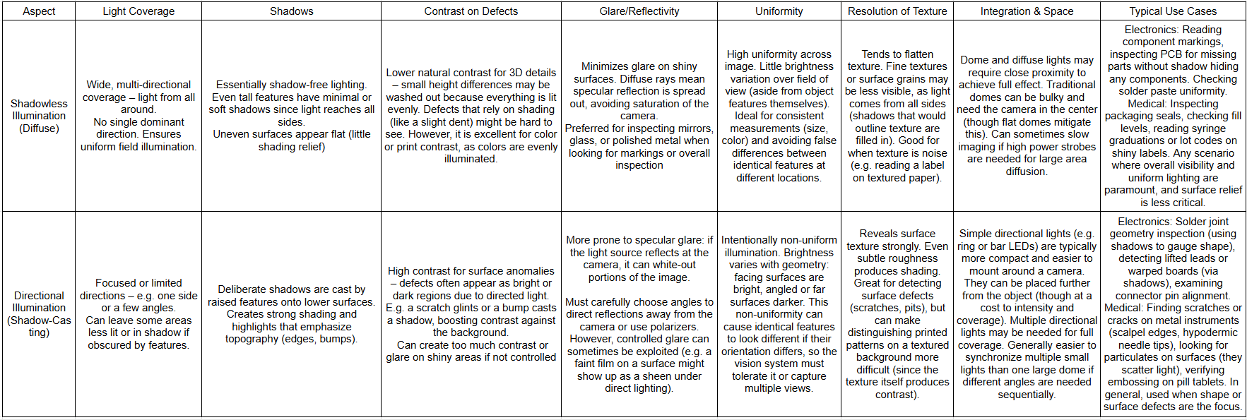
Both lighting approaches have distinct performance characteristics. Table 1 summarizes key differences and trade-offs between shadowless (diffuse) and shadow-casting (directional) illumination in machine vision:
Table 1: Comparison of Shadowless (Diffuse) vs. Shadow-Casting (Directional) Illumination
In practice, these two modes are not mutually exclusive but complementary. A diffuse light might be used to get a baseline image, then one or more directional lights add critical contrast for certain features. For instance, an electronics inspection might first use coaxial lighting to verify all components are present (no shadows hiding any part), then use a low-angle side light to highlight any lifted lead or excess solder as a shadow. The performance benefits come when each approach is used for what it does best: Shadowless for uniform detection of anything that shouldn’t be there, and shadow-casting for detecting what is there that shouldn’t be (anomalous features).
From a throughput perspective, using multiple lighting configurations can mean more images to capture and process. Some high-speed systems solve this by using multiple cameras, each with different fixed illumination, operating in parallel. Others use programmable LED banks that can switch lighting modes in microseconds, grabbing successive images that are later analyzed. The slight complexity overhead is usually justified by the significantly higher defect detection rates achieved when combining lighting methods, especially for challenging inspections.
Impact on Defect Detection Accuracy
Proper lighting design directly impacts the accuracy and reliability of defect detection in machine vision. An “excellent optical illumination platform” ensures high-quality images, which is a prerequisite for reliable automated inspection. Several aspects of accuracy are influenced by lighting:
- Detection Rate (Missed Defects): Using the right illumination can dramatically reduce missed defects (false negatives). For example, a recent study on inspecting highly reflective steel surfaces found that introducing a diffuse integrating-sphere light source improved the ability to consistently identify defects. The uniform lighting made defect features easier to extract and allowed more robust identification, decreasing the omission (miss) rate in categorizing defect types.
In other words, fewer defects were “invisible” to the system once glare was mitigated and lighting was even. Another case is scratch detection on surfaces: dark-field angled lighting often pushes detection rates much higher than using bright-field alone, because scratches that were barely perceptible in uniform light become starkly visible. Researchers reported ~82% detection of very shallow scratches using an optimized dark-field method, versus significantly lower with other illumination. These improvements show that aligning lighting to the defect’s visibility yields tangible gains in catching all true defects.
- False Alarms (False Positives): Conversely, poor or inconsistent lighting can increase false positives by making normal features look like defects. In AOI for PCB, if illumination is non-uniform across the field of view, identical components at different locations might appear with varying brightness. The vision software might then flag a perfectly good component as “different” (and thus defective) simply because it was lit differently – a classic false alarm. One industry analysis noted that if an AOI image suffers from brightness falloff toward the edges or has shadows, the system must loosen its thresholds to avoid false calls, which in turn reduces overall fault coverage.
Homogeneous, shadowless lighting is thus important for test reliability, ensuring the same part yields the same image features regardless of position or orientation. Shadowless lighting tends to reduce false positives in scenarios like presence/absence or assembly verification, because it avoids extraneous shadows or glares that might mimic a defect. On the other hand, if lighting is too diffuse, sometimes real defects can lack contrast and be mistaken for normal variation (a false negative scenario). So there is a balance: you want enough shadow/shading to uniquely identify real defects, but not so much that normal variations (like a slight curvature on a surface) produce shadows that trigger false alarms.
- Feature Highlighting and Segmentation: Good lighting maximizes the contrast between defects and the background, making it easier for image processing algorithms to segment and identify them. In machine vision, a “high-quality” image is one with sharp contrast where defects are clearly highlighted against non-defective areas. For instance, consider inspection of tablet pills for cracks: if lit diffusely from the front, a fine crack might show only a low-contrast line; but if lit from the side, that crack might cast a distinct dark line, allowing a simple threshold or edge detector to pick it up. Without that contrast, more complex algorithms or higher camera resolution would be needed, and still might miss the flaw. In short, appropriate lighting often simplifies the computer vision problem and boosts accuracy, whereas inadequate lighting forces the algorithm to work harder and often results in lower reliability. This is echoed in automated systems: one study on cylindrical metal part inspection used a shadowless ring light to avoid specular glare and successfully highlight defects, essentially preprocessing the image so that their machine learning model could achieve over 90% accuracy in classification.
The lighting solved the reflection problem that would have confused the algorithm, directly contributing to the high accuracy achieved.
- Spatial and Color Accuracy: In measurements or color inspections, lighting affects accuracy by introducing biases if not controlled. For example, measuring the width of a transparent medical tube might be inaccurate if shadows make the edges hard to locate. A backlight (shadowless silhouette) would give a crisp outline for precise measurement. Or checking the color of a pill: directional lighting might shadow one side, changing the perceived color. Regulated diffuse lighting (often per standards like ISO for color inspection) ensures the camera sees the true color evenly, thus the system accurately verifies the pill color is correct. Uniform intensity is also part of good manufacturing practice (GMP) in vision-based quality checks
, as uneven lighting could cause parts of an image to fall below detection thresholds or wash out details, compromising the consistency of quality assurance.
- Combined Lighting = Improved Accuracy: Many of the highest-accuracy inspection systems, as demonstrated in case studies, use a combination of shadowless and directional lighting to minimize both misses and false calls. The scalpel blade inspection study noted that using dark-field, coaxial, and dome together produced images where defects were “well-highlighted”, enabling efficient and accurate detection by the vision algorithms. Each type of light filled in a gap of the other – what one lighting might miss, another would catch – resulting in near-comprehensive detection. In PCB solder joint inspection, the introduction of angled colored lights (to supplement diffuse lighting) significantly improves classification of solder defects, as each defect type (insufficient solder, excess, misalignment) has a signature under certain lighting that becomes obvious. The impact on accuracy is that fewer genuine defects escape detection (lower escapes), and fewer good parts are flagged (lower false calls), leading to a higher overall defect detection accuracy percentage for the system.
In summary, lighting design profoundly affects defect detection performance. Shadowless lighting contributes to accuracy by providing consistency, reducing false triggers from extraneous shadows, and making sure no defect is hidden in darkness or glare. Directional lighting contributes by enhancing the visibility of the very features that define a defect, thus reducing the chance that a defect is overlooked. The optimal approach often mixes the two – using diffuse illumination as a base and targeted directional lights for specific defect modes – to achieve high contrast where needed and high uniformity everywhere else. Empirically, this leads to the most robust inspections, as evidenced by both academic research and industry AOI solutions
Lighting is a cornerstone of machine vision inspection, and choosing between shadowless or shadow-producing illumination is a fundamental design decision. Shadowless lights (dome illuminators, diffuse panels, etc.) offer uniform, glare-free images well-suited for general inspection, reading codes, and ensuring no area is occluded by shadows. They shine in applications like electronics assembly checks and medical package inspection, where even lighting ensures reliable detection of presence/absence and printed information. Shadow-casting lights (angled rings, bars, dark-field setups) provide the critical contrast needed to expose subtle surface defects and 3D features – making them indispensable for detecting micro-defects like scratches, cracks, or solder joint anomalies. These lights excel in highlighting edges and texture, benefiting tasks like solder quality analysis and surgical tool inspection.
Neither approach alone is a silver bullet for all inspections. As we’ve seen, they are often combined in advanced AOI systems to capitalize on each other’s strengths: diffuse lighting to avoid missing anything, and directional lighting to zero-in on specific flaws. The design principles – from constructing dome lights and flat diffusers to arranging multi-angle LED ring arrays – are all about controlling how light interacts with the object to reveal what needs to be seen. Application studies in both electronics and medical device domains consistently show that appropriate illumination design raises defect detection rates and lowers false errors, directly improving quality control outcomes
In practice, engineers must evaluate the target features: If the challenge is glare and uneven geometry, a shadowless approach is likely the starting point; if the challenge is lack of contrast for fine details, strategic directional lighting will be introduced. The impact on defect detection accuracy is profound – a well-lit system can catch defects more reliably and with less algorithmic complexity than a poorly lit one. Thus, mastering both shadowless and shadow-casting illumination techniques, and knowing when to deploy each, is essential for building robust machine vision inspections in electronics manufacturing, medical device production, and beyond. The ultimate goal is to produce images where every defect, whether it’s a missing electronic component or a hairline crack in a medical implant, stands out clearly for the vision system to detect with confidence.
